Introduction: Two Drawings, Two Engineering Decisions
In process engineering, a Process Flow Diagram (PFD) and a Piping & Instrumentation Diagram (P&ID) are often mentioned together. They may appear similar to new engineers because both use equipment blocks, process lines and symbols. In real project work, however, they answer very different questions.
A PFD answers: How does the process work? It explains the main equipment, primary process streams, flow direction and key operating data. A P&ID answers: How will the system be built, controlled, isolated, protected and operated? It adds valves, instruments, control loops, line numbers, drains, vents, safety devices and equipment tags.
This difference matters because engineering mistakes often start when teams use the wrong document for the wrong decision. A PFD is excellent for understanding a process concept, heat and mass balance or early design discussion. A P&ID is required when the team needs detailed piping, instrumentation, safety review, construction planning or commissioning information.
Quick Answer
- PFD means Process Flow Diagram. It shows the process concept and main flows.
- P&ID means Piping and Instrumentation Diagram. It shows detailed piping, valves, instruments and controls.
- A PFD is normally prepared first during concept design or FEED.
- A P&ID is developed later when the process is stable enough for detailed engineering.
- A PFD is not enough for construction. A P&ID is a key document for HAZOP, operation and maintenance.
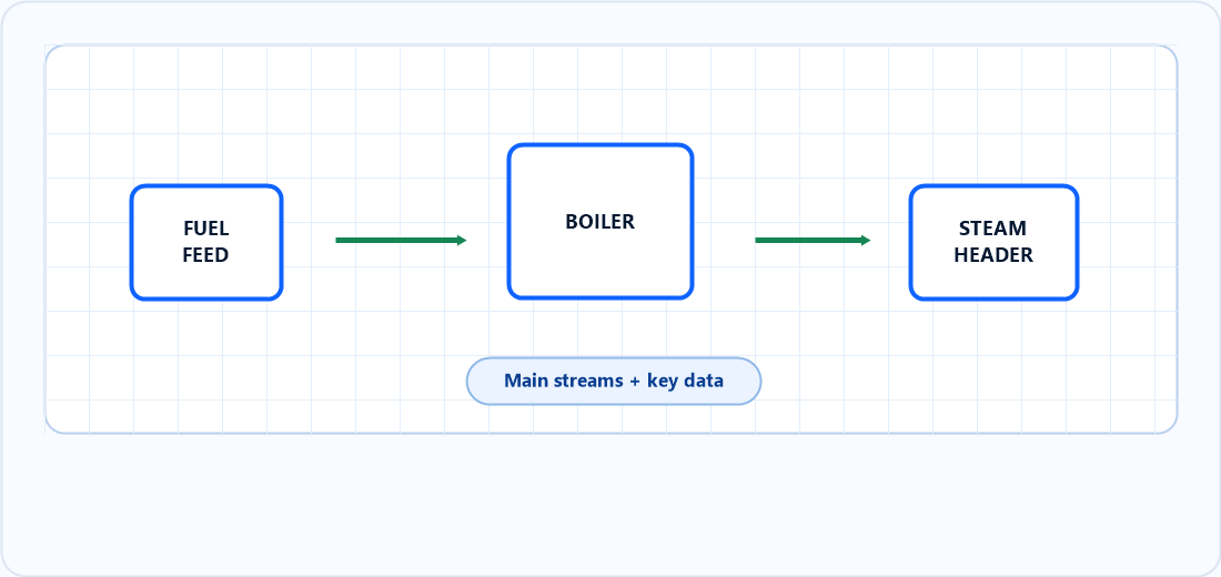
PFD: Process Overview
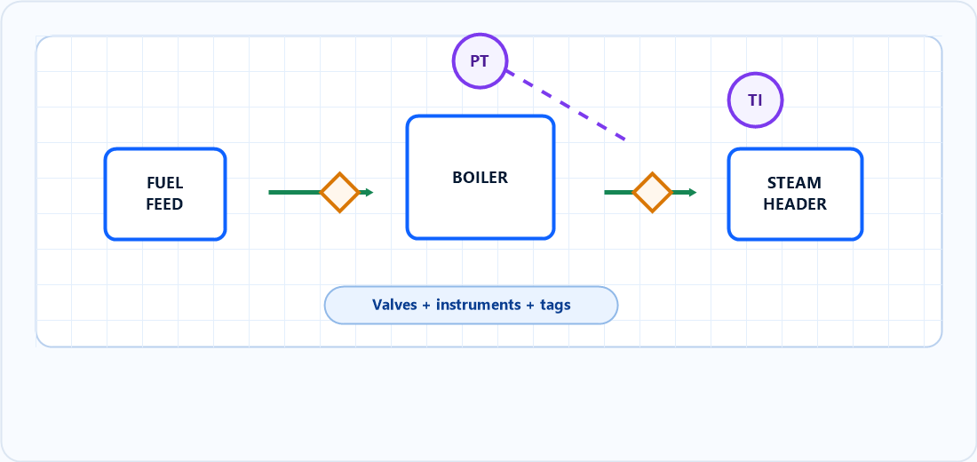
P&ID: Detailed Engineering
1. What Is a PFD?
A Process Flow Diagram is a high-level process drawing. It describes the main process route and shows how major equipment and streams are connected. It is normally used during process development, concept design, pre-FEED and FEED.
A typical PFD includes major equipment, main process lines, flow direction, stream numbers, key flow rates, operating pressure, operating temperature, heat duties and sometimes composition or utility data. It helps the team understand what the plant is trying to do before detailed piping and instrumentation decisions are made.
For example, in a biomass boiler system, a PFD may show fuel feeding, combustion air, boiler, economizer, air preheater, flue gas path, steam drum and main steam export. It may show steam flow, pressure, temperature, boiler capacity and flue gas temperature. It usually does not show every isolation valve, drain, vent, instrument signal or safety interlock.
2. What Is a P&ID?
A Piping & Instrumentation Diagram is a detailed engineering drawing. It develops the process shown on the PFD into a system that can be reviewed, controlled, built, operated and maintained.
A typical P&ID includes equipment tags, line numbers, pipe classes, valve types, instruments, control loops, safety valves, interlocks, drain and vent connections, bypass lines, sample points and utility tie-ins. It also shows how different disciplines connect their work: process, piping, mechanical, instrumentation, electrical, control and operations.
Because of this detail, P&IDs are usually controlled documents. A small P&ID change can affect procurement, pipe routing, control logic, safety review, commissioning procedure and maintenance access. That is why P&ID revision control is much stricter than many early-stage process sketches.
3. PFD vs P&ID Comparison Table
| Engineering question | PFD | P&ID | Why it matters |
|---|---|---|---|
| Purpose | Explain process concept | Define detailed design and operation | Prevents using overview drawings for detailed decisions. |
| Equipment | Main equipment only | All relevant equipment with tags | Supports equipment lists and discipline coordination. |
| Piping | Major process streams | Process, utility, drain, vent and bypass lines | Required for piping design and operation. |
| Valves | Usually omitted or simplified | Isolation, control, check, safety and special valves | Defines how the system is isolated and controlled. |
| Instruments | Limited key indicators | Detailed instrument tags and loops | Required for control philosophy and automation. |
| Line numbers | Usually not included | Included | Links the drawing to line lists and pipe specifications. |
| Safety review | Useful for process overview | Essential for HAZOP and operability review | Safety studies need valves, instruments and protections. |
| Construction use | Not enough | Core construction reference | Construction needs detailed piping and instrumentation. |
4. Typical Engineering Workflow
In a healthy project workflow, the PFD comes first. The process engineer uses it to define the route, mass balance, heat balance and major equipment. Once the process basis is stable, the team develops P&IDs to define piping, valves, instruments and control logic.
If the P&ID starts too early, the team may waste time detailing lines and valves around a process that is still changing. If the PFD stays too vague for too long, the P&ID team may make assumptions that later become expensive design changes.
5. When To Use Each Drawing
Use a PFD when the main task is process understanding. It is the right drawing for discussing capacity, process alternatives, equipment arrangement, energy balance, utility demand and major process performance. During early meetings, a clear PFD keeps the discussion focused on what the process must achieve.
Use a P&ID when the main task is engineering definition. It is the right drawing for line lists, valve philosophy, instrument selection, control loops, safety devices, HAZOP, commissioning and maintenance planning. During detailed design, the P&ID becomes the shared technical map for multiple disciplines.
Use PFD For
- Concept design and FEED
- Heat and mass balance
- Process route discussion
- Major equipment definition
- Client or management review
Use P&ID For
- Detailed engineering
- HAZOP and safety review
- Control philosophy
- Construction and commissioning
- Operation and maintenance
6. Biomass Boiler Example
The difference becomes clear in a biomass boiler plant. A PFD may show biomass fuel entering the boiler, combustion air entering the furnace, flue gas passing through heat recovery equipment and steam leaving the steam drum. This is enough to discuss capacity, efficiency, heat balance and main process behavior.
PFD Shows
- Boiler and steam drum
- Economizer and air preheater
- Fuel, air, flue gas and steam streams
- Main pressure, temperature and flow data
- Overall heat recovery concept
P&ID Adds
- Pressure transmitters and temperature indicators
- Control valves and isolation valves
- Safety valves, drains, vents and bypasses
- Line numbers and instrument tags
- Interlocks, trips and control connections
For operation and safety, the P&ID becomes critical. A missing drain, vent, bypass, pressure transmitter or safety valve may not be visible on a PFD, but it can affect startup, shutdown, maintenance and protection of the boiler system.
7. CADBoost Design Experience
In practical CADBoost engineering workflows, one common problem is that teams try to create a P&ID before the PFD and process basis are stable. The drawing may look detailed, but the process assumptions behind it are still moving. This creates repeated rework in line numbering, valve placement, instrument tags and control loops.
Another common issue is overloading a PFD with too much detail. A PFD should stay clean enough to explain the process. If it becomes crowded with every valve and instrument, it loses its purpose as a process communication tool. The better approach is to keep the PFD clear, then let the P&ID carry the detailed engineering information.
8. PFD and P&ID Review Checklist
| Review item | Check on PFD | Check on P&ID |
|---|---|---|
| Process route | Main flow path is logical and complete | All detailed connections follow the process route |
| Equipment | Major equipment is shown | Tags, nozzles and connections are coordinated |
| Operating data | Key flow, pressure and temperature are consistent | Instrument ranges and control points support operation |
| Isolation | Not normally detailed | Equipment and control valves can be isolated safely |
| Safety | Main relief or protection concept may be noted | Safety valves, trips, alarms and interlocks are defined |
| Maintenance | Limited use | Drains, vents, bypasses and access requirements are visible |
9. Common Mistakes
Using a PFD for detailed piping design
A PFD does not contain enough information for pipe routing, valve selection, instrument location or construction planning.
Adding every valve to a PFD
This makes the PFD hard to read and turns it into an incomplete P&ID. Keep the PFD focused on process logic.
Starting P&IDs before the process basis is stable
Premature P&ID work often creates rework in tags, line numbers, control valves and safety devices.
Treating PFD and P&ID symbols as interchangeable
P&ID symbols carry detailed engineering meaning. Instrument bubbles, signal lines and valve symbols must follow the project standard.
How CADBoost PFD Helps
CADBoost PFD is designed around the early process-engineering workflow. It helps engineers create clean process diagrams, reuse symbol libraries, attach engineering data and export clear documentation. This is especially useful before the project moves into detailed P&ID development.
The goal is not to replace engineering judgment. The goal is to make process documentation faster, more consistent and easier to review. A clear PFD gives the project team a stronger foundation before line lists, instrument lists and detailed P&IDs begin.
Learn More About CADBoost PFDFrequently Asked Questions
What is the main difference between a PFD and a P&ID?
A PFD shows the main process concept, major equipment and primary process streams. A P&ID shows detailed piping, valves, instruments, control loops, safety devices and tags required for engineering, operation and maintenance.
Which document is prepared first, PFD or P&ID?
The PFD is normally prepared first because it defines the process route, major equipment and heat and mass balance. The P&ID is developed later when the process concept is stable enough for detailed piping, instrumentation and safety review.
Can a PFD be used for construction?
No. A PFD is not detailed enough for construction. Construction and commissioning normally require P&IDs, piping drawings, line lists, instrument lists, equipment drawings and specifications.
Why are P&IDs important for HAZOP?
HAZOP requires detailed information about process lines, valves, instruments, interlocks, controls and safety devices. A P&ID provides the level of detail needed to review hazards, operability and protection layers.
Conclusion
PFDs and P&IDs are not competing documents. They are two stages of engineering thinking. The PFD explains the process. The P&ID defines the engineered system that will be controlled, protected, built and maintained.
A strong project uses both documents correctly. Start with a clear PFD to lock the process basis, heat balance and main equipment. Then develop a disciplined P&ID to define valves, instruments, controls, safety devices and operating details. When both drawings are used in the right sequence, the project becomes easier to review, easier to build and safer to operate.