Define the question
Agree on operating cases, performance indicators, constraints and acceptance criteria.
Turn complex flow behavior into a practical design decision with documented assumptions, quantified comparisons and clear engineering recommendations.
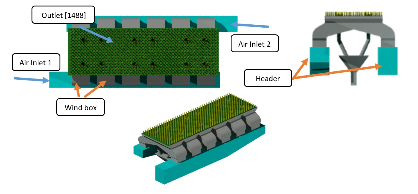
The model scope is selected around the engineering question—not simply around the largest possible geometry.
Efficient screening models can be used first, followed by higher-fidelity verification where it adds decision value.
Agree on operating cases, performance indicators, constraints and acceptance criteria.
Review geometry, fluid properties, boundary conditions and simplifying assumptions.
Quantify current behavior and confirm that the model answers the intended question.
Compare geometry or operating variants using consistent engineering metrics.
Check the preferred concept in 3D or at higher fidelity when justified.
Deliver results, limitations, implementation notes and recommended next actions.
A staged OpenFOAM workflow screened header and windbox baffle concepts, then verified the selected arrangements in three dimensions.
Depending on the decision, work may combine efficient 2D screening and 3D verification. Conservation checks, mesh sensitivity and comparison with measurements or reference data are included where the available information and project scope allow.
Every report identifies modeled physics, assumptions, exclusions and uncertainty relevant to interpreting the results. Cold-flow analysis, for example, is not presented as a combustion or emissions prediction.
Share the available geometry, operating information and the decision your project needs to make. CADBoostPro can review the information and propose an appropriate CFD scope.
Discuss your CFD project →What behavior needs to improve? Which operating cases matter? What measurements are available? What design changes are practical?