Installation checklist in one minute
- Freeze the approved design pressure, temperature, storage duty, operating levels and nozzle schedule before site work.
- Locate the vessel where foundations, lifting, inspection, drainage and future removal remain practical.
- Support the accumulator independently and prevent pipe loads from being transferred into vessel nozzles.
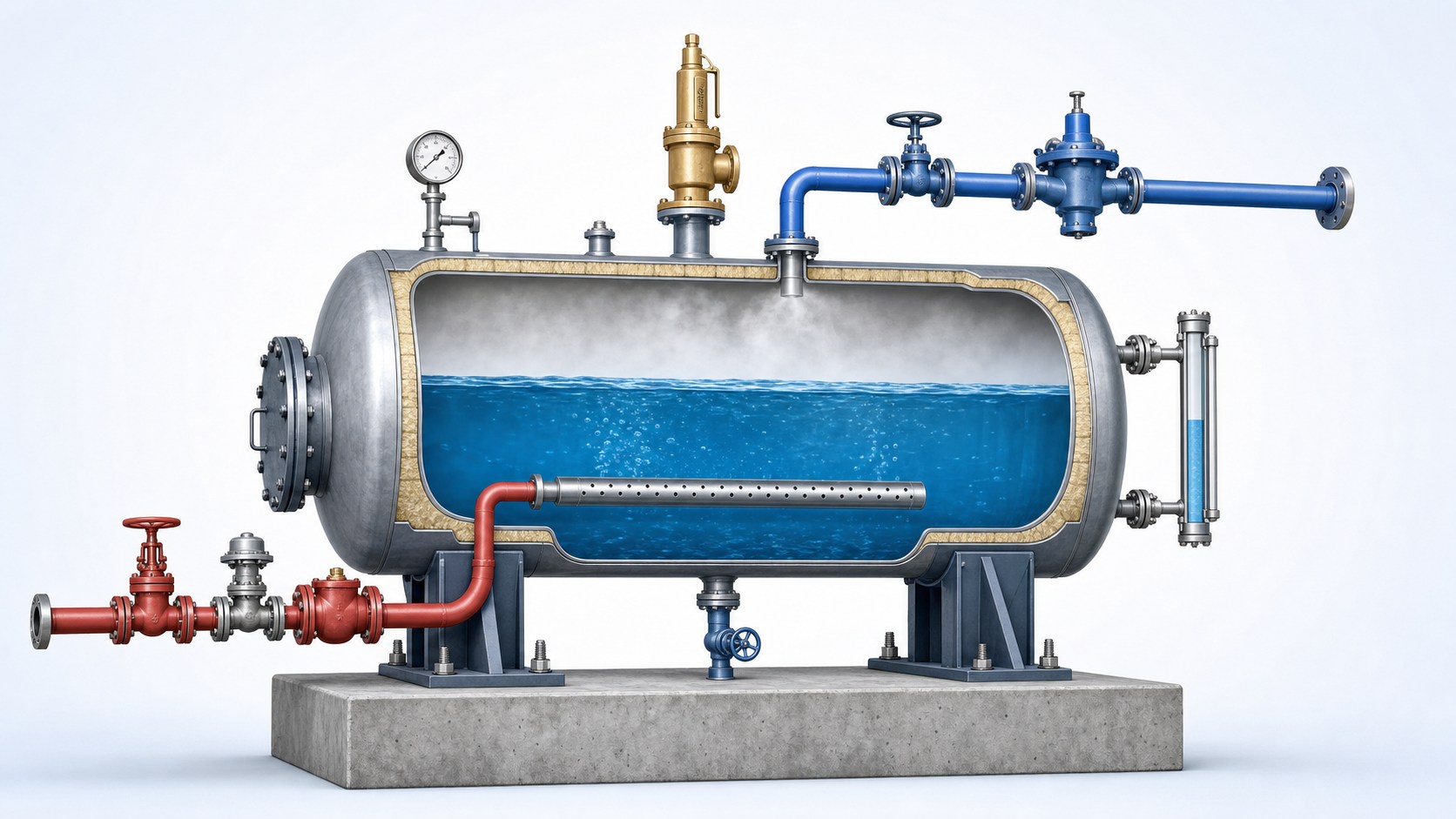
- Arrange charging steam to enter through the approved injector or distribution system below the water level.
- Take discharge steam from the top steam space and provide drainage for low points and pressure-control stations.
- Install pressure, level, temperature, isolation, non-return and protective devices exactly as required by the design.
- Complete examination, cleaning, instrument checks and documented commissioning before normal cyclic operation.
A correctly sized steam accumulator can still perform badly when installation details are treated as ordinary steam piping. The vessel stores a large mass of hot pressurized water, accepts charging steam through a substantial pressure difference and releases flash steam during a falling-pressure cycle. Nozzle loads, water level, drainage, steam quality, control-valve authority and access for examination all affect whether the installed system delivers the calculated capacity safely.
This guide explains the engineering workflow from layout review to commissioning. It is intended for project engineers, plant owners and installation teams coordinating a pressure-vessel supplier, piping contractor, controls team and competent inspection authority. It does not replace the vessel manufacturer's drawings, the applicable pressure-equipment code, local legal requirements or project-specific hazard review.
1. Confirm the design basis before installation
Installation begins with a coordinated design package, not with positioning the vessel. Confirm the approved vessel data sheet, general arrangement, nozzle schedule, allowable nozzle loads, support details, design pressure and temperature, material specification, corrosion allowance, insulation requirement and examination documentation. Compare these documents with the final steam-load profile and accumulator sizing calculation. A late change in operating pressure or fill ratio can affect stored capacity, safety-valve duty, control range and normal level markings.
The piping design should identify the charging source pressure, maximum charging flow, minimum usable discharge pressure, process peak flow, condensate loads and every operating case. Include startup, normal charging, standby, rapid discharge, recovery, shutdown and loss-of-utility scenarios. Define which party owns the mechanical design, supports, relief system, controls, inspection plan and commissioning procedure.
Do not use the thermal sizing result as an installation drawing
Accumulator volume and storage capacity do not define nozzle size, reinforcement, relief capacity, injector geometry, foundation loads or piping flexibility. Those items require approved mechanical and system design.
2. Choose the location and orientation
Horizontal accumulators are common because they provide a broad water surface and manageable overall height, but the manufacturer's orientation must be preserved. Select a location close enough to the boiler header and peak users to avoid unnecessary pressure loss while retaining safe access. Long charging or discharge lines add volume, heat loss, condensate and control delay. A convenient pipe route is not sufficient if the vessel becomes inaccessible for examination.
Provide working space around manways, inspection openings, safety valves, level instruments, drain valves and removable internals. Allow for insulation thickness and cladding removal. Check whether tube bundles, injectors or internal distribution pipes require straight withdrawal space. The layout must include a lifting route for valves and instruments and, where reasonably foreseeable, a route for future vessel replacement.
Locate the accumulator away from vehicle impact, corrosive releases, flooding and areas where a steam or hot-water discharge could expose personnel. Provide ventilation and safe drainage. Outdoor installations need weather protection, freeze protection for small-bore lines, durable cladding and a corrosion-under-insulation strategy. Indoor installations need adequate heat management and a safe route for relief and vent discharges.
3. Design foundations, saddles and anchors
The foundation must support the vessel at its maximum operating or test mass, not its empty shipping weight. A large accumulator may contain tens of tonnes of water. Consider the vessel, water inventory, insulation, platforms, piping reactions, hydrotest condition, wind, seismic demand and other loads required by the site design basis.
Use the support arrangement shown on the approved vessel drawing. Horizontal vessels commonly have two saddles, with one end arranged to accommodate thermal expansion. Incorrectly fixing both ends can introduce large shell and anchor loads as the vessel heats. Grouting, sole plates, anchor bolts and sliding surfaces must be installed to the specified elevations and tolerances. Survey the support levels before final tightening so the shell is not twisted to match an uneven foundation.
Do not use connected piping to pull a nozzle into alignment. Pipe supports should be completed and adjusted before the final flange connection. Verify nozzle loads against the manufacturer's limits and perform a flexibility or stress assessment where pipe size, temperature, weight or geometry makes reactions significant.
4. Install the charging-steam system
Charging steam must transfer energy into the water without damaging the vessel, causing severe vibration or allowing accumulator contents to flow backward into the supply header. The approved arrangement normally includes isolation, appropriate conditioning or drainage, a charging control valve, non-return protection and an internal injector or distribution pipe. The exact sequence depends on the design and site standard.
Steam entering the accumulator condenses below the water surface. The injector must distribute flow so condensation does not create unacceptable local shock, noise or shell loading. Do not replace a designed injector with an open nozzle or modify hole size and orientation at site without the vessel designer's approval. Confirm that internals are installed in the correct direction and are supported for hydraulic and cyclic loads.
The charging line should deliver dry steam. Provide drainage for low points and warm-up condensate, and review whether a separator is needed for the supply condition. Pitch the line according to the steam-system design and keep branch connections arranged to minimize condensate carryover. The control valve must have sufficient pressure-drop authority across the expected charging cycle; an oversized valve can hunt, while an undersized valve prevents recovery before the next peak.
Non-return protection is important because accumulator pressure can exceed upstream pressure during boiler trips or header disturbances. Select the check valve for steam service, differential pressure and installation orientation. Its presence does not remove the need for safe isolation and a defined lockout procedure.
5. Install the discharge and pressure-control system
Take discharge steam from the approved top connection where the driest steam is available. The outlet line must handle the maximum instantaneous flow, not only the average stored mass. Verify velocity, pressure loss and drainage from the accumulator to the process header. Excessive loss can make the lower portion of the calculated pressure range unusable.
A pressure-reducing or control station often separates variable accumulator pressure from a stable downstream process header. Size the valve for the complete upstream pressure range and required downstream flow. Check noise, outlet velocity and possible need for staged pressure reduction. Provide upstream and downstream pressure indication and follow the selected valve manufacturer's requirements for straight length, strainers, separators, drains and sensing-line location.
Steam lines and PRV stations must drain effectively during warming and low flow. Trapped condensate can cause water hammer just when the accumulator begins rapid discharge. Install drip legs and trap stations at the designed low points, before upward rises and around control stations as required. Do not connect drains in a way that permits backpressure or cross-flow to defeat trap operation.
6. Provide reliable level measurement
Operators need a direct and dependable indication of water level. Although only a fraction of the water mass flashes during a typical cycle, the level changes with pressure, density, steam formation and inventory. Provide the gauge glass or other local indication required by the vessel design, together with remote transmitters and alarms where the operating philosophy calls for them.
Instrument tappings must remain representative and free from steam or condensate pockets that distort differential-pressure measurement. Wet legs, condensing pots, impulse-line slope, heat tracing and equalizing arrangements should follow the instrument design. Mark the approved normal, high and low operating levels after the final commissioning basis is confirmed.
High level can reduce steam disengagement space and increase water carryover. Low level reduces available stored energy and may expose charging internals. Alarm and trip actions should therefore be defined from consequences, not copied from another vessel. Test the entire loop from sensing point to alarm, control action and operator display.
7. Install pressure protection, venting and vacuum safeguards
The accumulator and any blocked-in sections must be protected against credible overpressure. Relief-device sizing and set pressure belong to the approved pressure-system design. Consider charging-valve failure, upstream pressure, heat input, isolation arrangements and other project-specific scenarios. Install the safety valve directly and independently enough that isolation, pressure loss or condensate cannot compromise its function.
Route the discharge to a safe location, support the discharge pipe independently and account for reaction forces, drainage and backpressure. Never use relief discharge piping as a convenient structural support. Ensure test levers, lifting mechanisms and seals remain accessible when permitted by the selected device and site rules.
A high point vent or air-purge connection may be needed during filling and initial pressurization because trapped air reduces heat transfer and corrupts pressure-temperature interpretation. Vacuum protection may also be required where steam condensation during cooldown can pull the vessel below its allowable external pressure. The need and device capacity must be assessed rather than assumed.
Pressure systems are regulated differently by jurisdiction. As one example of the underlying safety principle, UK HSE pressure-system guidance treats the vessel, associated pipework and protective devices as a pressure system and requires defined safe operating limits and examination by a competent person under an appropriate written scheme. Projects elsewhere should identify the equivalent local obligations before operation.
8. Arrange drains, blowdown and water quality
Provide a bottom drain at the approved low point so the vessel can be emptied for inspection and maintenance. The discharge contains pressurized hot water and may flash violently when pressure is reduced. Route it to a suitably designed blowdown vessel, flash tank or other safe system; never treat it as an ordinary floor drain.
Small-bore instrument drains, steam-line drip legs and vessel drains serve different functions and should be shown separately on the P&ID. Make valves accessible without placing the operator in the discharge path. Provide means to verify isolation and depressurization before opening the vessel.
Accumulator water is part of the steam-water system, so boiler-water chemistry, corrosion products and contamination matter. Establish flushing and sampling provisions. Deposits can block injector holes, foul level connections and collect at the bottom of the vessel. Coordinate water-quality limits and chemical treatment with the boiler and condensate-return strategy.
9. Define the operating and control philosophy
The controls should distinguish charging, ready, discharging, recovery and shutdown states. A common objective is to charge when boiler-header capacity is genuinely available while preventing the charging demand from destabilizing boiler pressure. During a peak, the accumulator supplies steam as its pressure falls through the usable range.
Define permissives for adequate level, open isolation valves, healthy instruments and downstream availability. Specify what happens after loss of power, air, boiler steam, level signal or downstream demand. Control valves should move to the state established by the hazard review. Alarms need clear operator actions rather than generic labels.
Trend accumulator pressure, water level, charging-valve position, upstream and downstream pressure, process demand and relevant boiler output. These signals demonstrate whether the real cycle matches the sizing basis and make later troubleshooting possible. A “ready” indication should reflect restored pressure and energy inventory, not merely elapsed time.
10. Complete piping, insulation and identification
Steam and hot-water piping expands substantially from cold installation to operating temperature. Confirm guides, anchors, spring supports and flexible legs before insulation hides the route. Verify that valves can be operated, strainers can be opened and traps can be maintained without dismantling unrelated pipework. Temporary shipping supports must be removed where instructed.
Insulate the vessel, steam lines and hot fittings to reduce heat loss and protect personnel. Keep removable covers around manways, nameplates, safety valves and examination points. Seal outdoor cladding against water ingress while allowing intended drainage. Label charging, discharge, vent, drain and instrument lines and mark flow direction and valve function.
11. Installation quality checks
| Check | What to verify | Record |
|---|---|---|
| Vessel identity | Nameplate, serial number, design conditions and documentation match the approved item. | Receiving and turnover record |
| Foundation | Elevation, level, grout, anchors, fixed/sliding saddle arrangement and test load basis. | Survey and civil inspection |
| Internals | Injector orientation, supports, cleanliness and closure before manway installation. | Internal inspection photographs |
| Piping | Line class, slope, supports, drainage, valve direction, gasket and bolt control. | Line check and pressure-test pack |
| Instruments | Ranges, calibration, impulse lines, alarms, trips and displayed engineering units. | Calibration and loop-check sheets |
| Protective devices | Identification, certification, set pressure, inlet/discharge arrangement and accessibility. | Safety-valve register |
| Examination | Required initial examination and continuing inspection scheme are complete. | Competent-person documentation |
12. Pre-commissioning and first startup
Before admitting steam, confirm mechanical completion, pressure-test status, flushing, cleanliness, reinstatement and closure records. Remove temporary blinds only through the controlled line-up process. Verify safety valves, pressure gauges, level indication, transmitters, control valves, check valves, traps and alarms. Confirm that relief, vent and drain discharge routes are clear and safe.
Fill the vessel with water of the approved quality using the defined method. Vent trapped air while filling and during controlled warming. Bring the system up to temperature slowly enough to limit thermal shock and differential expansion. Inspect supports, flanges, small-bore connections and drains as temperature rises. Never tighten leaking pressure joints while following an unsafe or unauthorized procedure.
During initial charging, limit the flow and observe noise, vibration, level response and pressure-temperature behavior. Confirm that steam condenses smoothly through the injector. Approach normal charging pressure in stages, holding where required for inspection. Test alarms and protective functions using approved methods that do not defeat the safety system.
Commission discharge with a controlled process demand. Record upstream pressure, accumulator pressure, downstream pressure, valve position, level and flow. Confirm that the PRV remains stable, steam lines drain correctly and the process receives acceptable steam quality. After the first complete cycle, verify recovery time against the design calculation.
13. Performance acceptance
Acceptance should compare the installed system with the agreed operating cases. Demonstrate usable stored mass or peak duration, minimum downstream pressure, recharge time, maximum charging rate, stable control, acceptable steam quality and correct alarm response. Review boiler behavior as well as accumulator behavior; a fast charge that destabilizes the boiler is not a successful result.
Allow for instrument uncertainty and heat loss when comparing field data with an ideal calculation. If capacity is lower than expected, investigate actual pressure range, water level, valve pressure loss, unplanned continuous demand, incomplete recharge, wet steam, heat loss and instrument accuracy before concluding that vessel volume is inadequate.
14. Common installation mistakes
No access allowance
Platforms, piping or walls block manway opening, gauge-glass service or safety-valve removal.
Poor line drainage
Condensate accumulates before the discharge valve or in a low point, creating water-hammer risk.
Pipe strain at nozzles
Misaligned or inadequately supported piping transfers weight and thermal movement into the vessel.
Wrong injector details
Site modifications create uneven condensation, vibration or local loading not included in the design.
Unusable pressure range
Piping and PRV losses consume the lower pressure range assumed in the storage calculation.
Incomplete commissioning data
The plant starts production without a baseline trend for pressure, level, flow and recovery time.
15. Plan inspection and maintenance from day one
Installation must support the future examination strategy. Provide isolation, depressurization, draining, venting, access, lighting and safe entry arrangements. Keep the vessel nameplate visible and maintain a register of the vessel, protective devices, instruments and associated pressure-system components.
Routine work may include safety-valve certification, gauge-glass service, transmitter calibration, trap testing, injector inspection, internal deposit removal, thickness examination and insulation inspection. Frequencies depend on the applicable inspection scheme, operating severity, water chemistry, cycling and observed damage mechanisms.
For a broader description of accumulator ancillary equipment and operating principles, see the official Spirax Sarco Steam Accumulators module. Use it as general technical guidance alongside the selected vessel manufacturer's instructions and the requirements that apply to the installation location.
Frequently asked questions
Should a steam accumulator be installed near the boiler or near the process?
The best location balances charging and discharge pressure loss, control response, pipe cost, safety, foundations and maintenance access. A hydraulic and layout review is better than a universal distance rule.
Can the charging line connect directly to a vessel nozzle?
Only when that arrangement is part of the approved design. Most systems require an internal injector or distribution arrangement to condense steam below the water surface without unacceptable shock or vibration.
Why is a check valve required in the charging line?
Accumulator pressure may exceed upstream pressure during some disturbances. Non-return protection helps prevent reverse flow, but it does not replace safe isolation, controls or hazard review.
Does the accumulator need a pressure-reducing valve?
Many installations use one to provide stable downstream pressure while accumulator pressure falls. The requirement and arrangement depend on process pressure, usable pressure range and control philosophy.
Can the safety valve discharge into the plant steam header?
Relief discharge must follow the approved relief-system design. Backpressure, isolation, reaction forces and personnel exposure make improvised connections unsafe.
When is the installation ready for production?
After mechanical completion, required examination, instrument and protective-device checks, controlled warming, charging and discharge tests, and documented acceptance against the design operating cases.