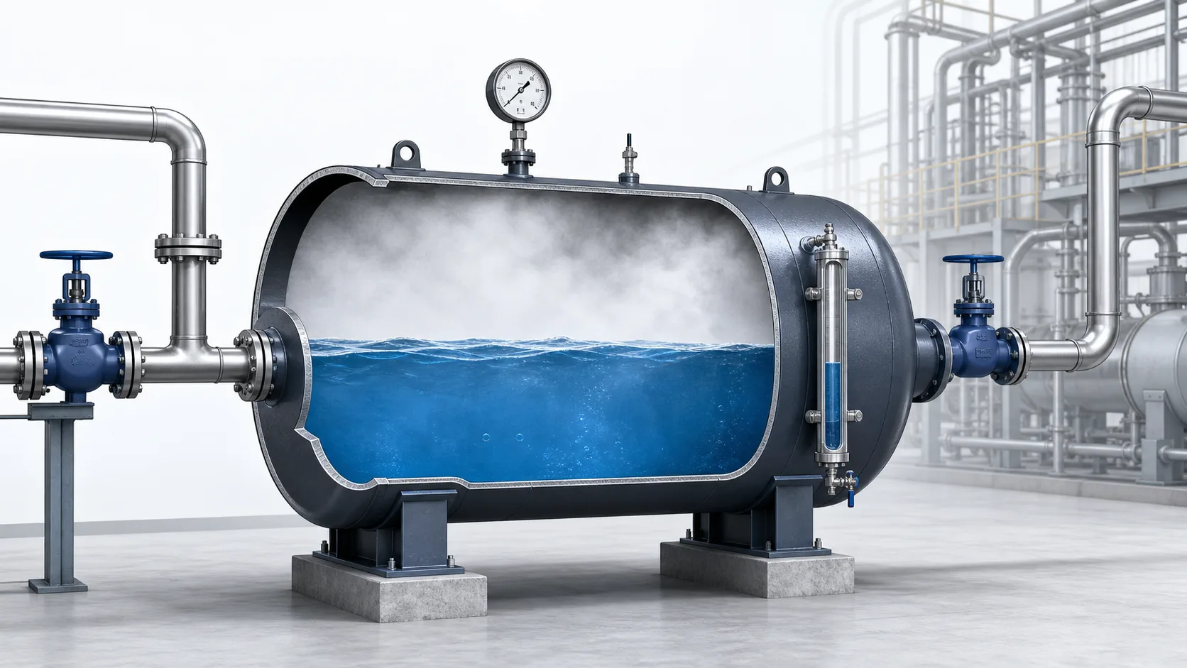
Steam accumulator in brief
- It is a pressure vessel containing saturated water and steam.
- It absorbs surplus boiler output when demand is low.
- It releases flash steam when plant demand rises above boiler output.
- It is most valuable where steam demand is intermittent, rapid or highly variable.
- It stores thermal energy; it does not create energy or replace adequate boiler capacity.
What is a steam accumulator?
A steam accumulator is an insulated pressure vessel used to store thermal energy in the form of pressurized, high-temperature water. A steam space is maintained above the water level. During periods of low plant demand, the boiler supplies more steam than the process requires. The surplus steam enters the accumulator, condenses in the water and raises its temperature and pressure. During a demand peak, pressure in the steam main and accumulator falls. Part of the hot water then flashes into steam and flows to the process.
This behavior makes the accumulator a buffer between a relatively steady steam source and a rapidly changing steam load. The boiler can operate nearer a stable firing rate while the accumulator handles short-duration peaks. In electrical terms it resembles a battery, but the analogy has limits: the stored quantity is thermal energy within saturated water, not a fixed mass of compressed steam waiting in an empty tank.
Industrial accumulators are normally horizontal cylindrical vessels because this arrangement offers a large water surface, practical vessel fabrication and stable level control. Vertical arrangements are possible, but vessel geometry, available space, nozzle arrangement, internal steam distribution and required disengagement area must all be considered. The vessel is designed to the applicable pressure-vessel code and is fitted with safety valves, pressure and level instrumentation, isolation, drainage and suitable steam connections.
Why are steam accumulators used?
Many boilers respond more slowly than the processes they serve. A burner, grate or fuel-feeding system needs time to increase heat release. Water circulation and evaporation also have thermal inertia. In contrast, an autoclave, tire press, veneer dryer, sterilizer or batch reactor may demand a large steam flow almost immediately. If the boiler alone must follow that step change, header pressure can collapse before firing catches up.
A falling header pressure affects much more than the pressure gauge. Control valves may open fully, heat-transfer temperature differences fall, process cycles lengthen and distant users compete for steam. The boiler control may overreact, causing pressure overshoot after the short peak has passed. Repeated cycling increases fuel consumption, emissions and equipment wear. An accumulator supplies the missing steam during the peak and absorbs excess generation afterward, smoothing both pressure and boiler load.
Process benefits
More stable steam pressure, faster batch heating, fewer production delays and reduced interaction between simultaneous steam users.
Boiler-house benefits
Smoother firing, fewer rapid load swings, improved combustion stability and less reliance on oversized standby capacity for brief peaks.
How does a steam accumulator work?
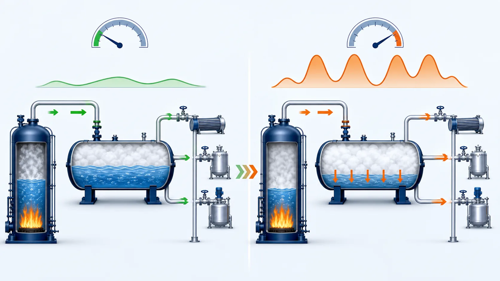
1. Charging period
Charging occurs when boiler output exceeds the instantaneous process demand. Steam enters through a connection designed to distribute it effectively within the vessel. Depending on the design, the steam may be introduced below the water surface through a sparger or handled through another engineered arrangement. It condenses and transfers latent heat to the stored water. As energy is added, the saturation temperature and vessel pressure rise toward the selected charging pressure.
Charging must be controlled. Excessively rapid steam admission can produce water hammer, vibration, noise and local thermal stress. Good distribution encourages mixing and avoids strong temperature stratification. The charging valve, non-return protection and control logic should coordinate with boiler pressure and steam-main conditions. The accumulator is fully charged thermodynamically when the water has reached the saturation state corresponding to the upper operating pressure, not simply when a level indicator reaches a certain mark.
2. Standby or balanced period
When boiler generation approximately equals plant demand, little net energy enters or leaves the vessel. The accumulator remains at pressure and is ready to respond. Real systems still lose heat through insulation and may experience small flows as control valves modulate. Proper insulation is therefore important, particularly for accumulators that wait for long intervals between demand peaks.
3. Discharging period
When process demand exceeds boiler output, steam-main pressure begins to fall. The accumulator discharge path opens or permits flow, depending on the control arrangement. Because the stored water is hotter than the saturation temperature at the new lower pressure, a fraction of it instantly evaporates. This is flash steam. The energy required for evaporation comes from the sensible heat of the remaining water, which cools as pressure falls.
Discharge continues until the lower design pressure is reached, the demand peak ends or another operating limit intervenes. Only a fraction of the stored water becomes useful steam during one cycle. The water inventory largely remains in the vessel and is reheated during the next charging period. This is why accumulator capacity depends strongly on water mass and the difference between upper and lower pressures.
The thermodynamics behind stored steam
The calculation is based on mass, volume and energy balances together with saturated-water properties. At the charging pressure, the vessel contains a mixture of saturated liquid and saturated vapor. The initial water fill ratio determines the phase volumes, but because liquid water is much denser than steam, most of the vessel mass is liquid.
During discharge the vessel volume is essentially constant. Pressure and saturation temperature decrease, some liquid flashes, and steam leaves the vessel. A rigorous calculation tracks the changing internal energy of the remaining mixture and the enthalpy carried out by discharged steam. Engineering software normally obtains density, specific volume, enthalpy, internal energy and entropy from the IAPWS-IF97 water-and-steam formulation.
The simplified relationship is useful for intuition: more water mass and a wider useful pressure range generally increase storage. However, neither variable can be increased without limits. The vessel must retain adequate steam disengagement space, stay within code pressure and temperature limits, satisfy process pressure requirements and avoid unacceptable moisture carryover.
Do not size by vessel volume alone
Two vessels with the same geometric volume can provide different useful steam capacity if their fill ratio, charging pressure, discharge pressure or allowable operating cycle differs. Steam demand rate and peak duration must be defined before vessel volume is selected.
How is a steam accumulator sized?
Sizing begins with the process load profile, not with a catalogue vessel size. The designer should determine the normal boiler contribution, peak process demand, duration of the peak, time available for recharge and acceptable pressure range. A demand curve is more useful than a single maximum flow because it shows how much steam is missing at each moment.
The required discharge mass is the time integral of the deficit between process demand and steam generation. For a simple rectangular peak, it may be approximated as the flow deficit multiplied by duration. Real batch processes often have ramps, holds and overlapping cycles, so a time-step calculation gives a better result. The accumulator is then selected so its usable release between upper and lower pressures meets or exceeds that required mass with a suitable design margin.
- Define the demand profile. Record each major steam user, its peak flow, start time, ramp rate and duration.
- Establish boiler contribution. Use a sustainable operating capacity, accounting for boiler pressure, fuel, controls and other continuous users.
- Select operating pressures. The upper pressure must suit the steam source and vessel design. The lower pressure must still satisfy the process after distribution and control-valve losses.
- Calculate required steam release. Integrate the demand deficit across the critical peak period.
- Calculate thermodynamic storage. Use saturated properties and an energy balance to determine the water mass and vessel volume required.
- Check recharge time. Confirm the boiler has enough spare output between peaks to restore the accumulator before the next cycle.
- Verify vessel and system details. Check steam velocity, disengagement space, nozzles, internals, safety valves, supports, drainage, insulation and control response.
Key design parameters
| Parameter | Why it matters | Common design concern |
|---|---|---|
| Upper charging pressure | Sets the high-energy saturation state. | Must remain below vessel design pressure with required margins. |
| Lower discharge pressure | Defines how much sensible energy can be converted into flash steam. | Must still provide adequate pressure at the process user. |
| Water fill ratio | Controls stored water mass and available steam space. | Too high can increase carryover risk; too low reduces storage. |
| Peak steam demand | Determines the required delivery rate. | Nozzles and piping must handle flow without excessive pressure loss. |
| Peak duration | Determines the total steam mass required. | A short high peak and a long moderate peak can require different designs. |
| Recharge time | Sets the required surplus boiler flow after discharge. | Closely spaced batches may prevent full recharge. |
Typical steam accumulator applications
Steam accumulators are best suited to plants where demand varies much faster than a boiler can follow. Traditional applications include textile finishing, rubber curing presses, autoclaves, sterilizers, laundries, breweries, food retorts, batch reactors, veneer and board presses, paper-machine peak loads and other cyclic heating processes. They can also support a steam network when several users occasionally start together.
An accumulator is less attractive when demand is continuously high and steady. In that case, additional boiler capacity, heat recovery or process optimization may be more appropriate. It also cannot solve a distribution system with undersized piping, failed traps, wet steam or poor pressure control. The designer must identify whether the real limitation is generation, storage, distribution or process operation.
Main components and system arrangement
The pressure vessel is only one part of a functioning installation. A complete system typically includes steam charging and discharge connections, an internal distributor where required, level measurement, pressure indication and transmitters, safety relief valves, isolation valves, non-return protection, drain and blowdown connections, air venting provisions, insulation and structural supports. Instrument selection should reflect high temperature, cycling and the consequences of false readings.
Controls vary with plant philosophy. Some systems respond directly to steam-main pressure; others coordinate accumulator valves with boiler master control or batch scheduling. The objective is to charge without disturbing normal users and discharge early enough to prevent a severe pressure dip. Valve sizing is critical: an oversized valve can be difficult to control, while an undersized valve restricts peak delivery.
Piping should be arranged to manage condensate and thermal expansion. Steam lines require appropriate slope, drainage and trapping. Supports must allow expansion without transferring excessive nozzle loads to the vessel. Safety-valve discharge must be routed safely, and the relief capacity must be established for credible overpressure scenarios rather than copied from a similar-looking installation.
Operational and safety considerations
A steam accumulator is a pressure vessel containing a large inventory of hot water. Its stored energy is substantial, so design, fabrication, inspection and operation must follow the applicable pressure-equipment regulations and site standards. The online calculator linked below is useful for preliminary engineering, but it does not replace code calculations, mechanical design or review by a qualified engineer.
- Maintain reliable level indication and independent protection against abnormal high or low level.
- Test safety valves and pressure instruments at the required intervals.
- Control warm-up and charging rates to limit thermal shock and water hammer.
- Inspect insulation, supports, nozzles and cyclic fatigue-sensitive areas.
- Monitor water chemistry and solids concentration where the accumulator shares boiler water.
- Confirm that isolation procedures address trapped pressure and high-temperature water.
Operating data should be trended over complete cycles. Useful signals include boiler steam flow, process flow, accumulator pressure, water level, charge-valve position and batch timing. Trends reveal whether the accumulator fully recharges, whether simultaneous loads have changed and whether controls are responding at the correct pressure. A vessel sized from an old production schedule may become inadequate after cycle times or equipment are modified.
Steam accumulator versus common alternatives
An accumulator is not automatically the best solution to every peak. A larger boiler provides sustained capacity but may operate inefficiently at low load. A second boiler adds flexibility and redundancy but increases capital cost, maintenance and operator requirements. Process scheduling can reduce overlapping peaks with little hardware, although production constraints may limit this option. Local hot-water storage or direct process thermal storage may be better when the user does not actually require steam.
The preferred solution is found by comparing the shape and frequency of the peak, fuel efficiency, pressure stability, redundancy, plant space and lifecycle cost. Accumulators are particularly effective when a large short-term peak is followed by enough low-demand time for recharge. They are less effective when the deficit lasts for hours and there is no surplus generation available afterward.
Frequently asked questions
Does a steam accumulator store steam?
It contains steam, but most of its useful energy is stored in the large mass of pressurized hot water. When pressure drops, part of that water flashes and becomes the steam delivered to the process.
Can a steam accumulator increase boiler capacity?
It can temporarily deliver steam above the boiler's instantaneous output, but it does not increase total energy generation. The boiler must later provide surplus steam to recharge it.
What determines accumulator capacity?
The principal factors are water mass, upper and lower operating pressures, initial fill ratio, thermodynamic properties and the usable discharge cycle. Process demand and duration determine how much capacity is required.
Why not fill the vessel completely with water?
A steam space and disengagement area are needed for stable operation and dry steam release. Excessive water level can contribute to entrainment and carryover into the discharge line.
👉 Try our Free Steam Accumulator Calculator
↓