Steam accumulator sizing in one minute
- Measure the steam demand profile and identify the load above sustainable boiler output.
- Integrate that deficit over time to obtain the required steam mass.
- Select upper and lower accumulator pressures that the source, vessel and process can actually use.
- Calculate how much useful steam each kilogram of hot water can release across that pressure range.
- Convert the required water mass into vessel volume using the operating fill ratio.
- Verify recharge time, steam release rate, controls, piping and pressure-vessel requirements.
If you are new to the equipment, begin with What Is a Steam Accumulator?. This article focuses on the next engineering question: how large the accumulator must be for a defined process load.
1. Working principle that controls the size
A pressure-drop steam accumulator is a pressure vessel partly filled with hot water at saturation temperature. During low demand, surplus boiler steam is injected below the water surface. The steam condenses, raising the water temperature and vessel pressure. During a peak, pressure falls and part of the stored hot water flashes into steam.
The useful reserve is therefore stored mainly as thermal energy in water, not as a large static mass of vapor. This explains why sizing depends on water inventory and pressure range. A physically large steam space alone provides relatively little storage because saturated steam is far less dense than liquid water.
2. Determine the required steam storage
Do not begin with vessel diameter or catalogue volume. Begin with a time-based steam balance. At each time step, compare process demand with the steam that the boiler can sustainably contribute without unacceptable pressure loss or carryover.
The required storage mass is the area under the positive portion of that deficit curve:
For a rectangular peak, the integration becomes a simple multiplication:
Use sustainable boiler contribution
Do not automatically subtract the boiler nameplate rating. Continuous users, burner response, feedwater conditions and operating margin may reduce the output genuinely available during the peak.
3. Select the operating pressure range
The upper charging pressure is normally slightly below the available boiler or high-pressure header condition after allowing for control-valve and piping losses. It must remain within the vessel's approved working pressure and the plant operating philosophy.
The lower discharge pressure is not simply the lowest pressure that produces steam. It must still overcome the pressure-reducing station, distribution losses and elevation while maintaining the minimum pressure required by the process user. A wider pressure range generally releases more useful steam per kilogram of water, but only the pressure range usable by the system counts.
| Selection | Engineering basis | Typical mistake |
|---|---|---|
| Charging pressure P1 | Available source pressure under real charging flow. | Using vessel design pressure as the normal charging pressure. |
| Discharge pressure P2 | Minimum accumulator pressure that still supports the plant. | Ignoring PRV and piping pressure loss. |
| Plant pressure | Pressure required at the user during peak flow. | Checking static pressure but not peak-flow pressure. |
4. Formula explained: from storage mass to vessel volume
At the charged state, saturated-water properties are evaluated at P1. At the discharged state, they are evaluated at P2. A control-volume energy balance accounts for the reduction in the internal energy of the vessel contents and the enthalpy carried away by discharged steam.
In preliminary hand calculations, engineers may use steam-table flash fractions or useful storage per kilogram of water. A computational approach is preferable because liquid and vapor volumes, mass, internal energy and outlet enthalpy all change with pressure. CADBoostPro evaluates saturated properties with IAPWS-IF97 and solves the two end states consistently.
Once the required water mass is known, the corresponding liquid volume at the charged state is:
If the selected operating fill ratio is F, preliminary vessel volume is:
The remaining volume provides steam space and disengagement area. A high fill ratio increases stored water but can reduce steam quality and operating margin. The final geometry therefore requires a release-velocity and carryover check, not just an energy calculation.
5. Design example
Consider a preliminary 20 m³ horizontal accumulator charged to 10 bar(g) and discharged to 5 bar(g), with an initial water fill ratio of 90%. The process steam demand is 2,000 kg/h and the available recharge period is 30 minutes.
The supply-time check is straightforward:
The recharge-rate check is:
This example means the boiler system must have approximately 1,672 kg/h of genuine surplus capacity for 30 minutes after the peak if the accumulator is to be fully ready for the next identical event. If that margin is unavailable, the design needs a longer recovery period, a different production schedule or additional generating capacity.
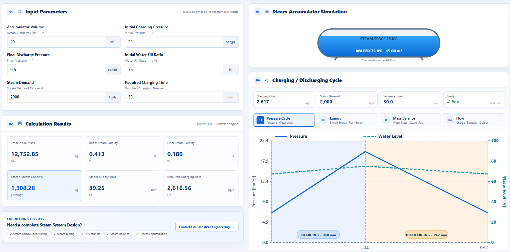
6. Use the Steam Accumulator Calculator
Enter vessel volume, charging pressure, final discharge pressure, water fill ratio, steam demand and required charging time. The tool reports total mass, steam quality, stored-steam capacity, supply time and charging rate. Use the four cycle tabs to inspect pressure and water level, stored energy and flash steam, liquid and vapor mass, and charging/demand/output flow.
Open Steam Accumulator Calculator →
Read the step-by-step calculator tutorial →
7. Practical design checks after the volume calculation
Steam release rate
Check the peak mass flow per unit water-surface area. Excessive release velocity can entrain water and produce wet steam.
Recharge capacity
Confirm that surplus boiler output and the interval between peaks can restore the full energy inventory.
Steam space
Provide adequate disengagement volume above the maximum operating water level.
Piping and valves
Size charging lines, injectors, discharge piping and PRVs for their actual differential pressure and peak flow.
Controls and protection
Define pressure, level, overflow, non-return, isolation, relief, venting and vacuum-breaker requirements.
Mechanical design
Complete pressure-vessel code, nozzle-load, support, fatigue, insulation and inspection calculations.
As a screening check, Spirax Sarco notes that dry-steam release depends on absolute pressure and available water surface, and therefore vessel geometry may need adjustment even when total volume is adequate. Their published guidance also emphasizes sizing from peak storage demand and allowable pressure drop rather than vessel volume alone. See the Spirax Sarco steam accumulator module for its worked industrial example and ancillary-equipment discussion.
8. Applications that benefit from accumulation
Steam accumulation is most valuable when a short or cyclic peak is much higher than average demand and enough low-load time exists afterward for recharge. Typical applications include autoclaves, sterilizers, rubber presses, textile finishing, food retorts, breweries, batch reactors, laundries, steam peeling and simultaneous start-up of several process users.
It is less effective when the deficit is continuous or when the boiler never has spare output. In those cases, extra generating capacity, heat recovery, process rescheduling or local thermal storage may be more appropriate.
Frequently asked questions
What information is required to size a steam accumulator?
At minimum, obtain the time-based process demand, sustainable boiler contribution, peak duration, charging pressure, minimum usable discharge pressure, operating fill ratio and time available for recharge.
Can vessel volume be calculated from peak flow alone?
No. Peak flow determines delivery rate, while peak duration determines total required mass. Pressure range and water inventory then determine how much vessel volume is needed to supply that mass.
Should steam demand or boiler deficit be entered?
For system sizing, the accumulator must cover the portion of demand not supplied by the boiler during the peak. If the boiler supplies part of the process load continuously, use the deficit profile for required storage.
Why not maximize the water fill ratio?
More water increases energy storage, but the vessel also needs steam space and surface area for disengagement. Excessive level increases the risk of water entrainment and unstable operation.
How do I know whether the accumulator is ready for the next batch?
Pressure, water temperature, water level and stored-energy target must be restored before the next discharge. The available surplus boiler flow multiplied by recovery time must at least replace the released steam and heat losses.
Is the online result sufficient for fabrication?
No. It is a preliminary thermal sizing result. Fabrication requires pressure-vessel code design and specialist checks for geometry, internals, nozzles, safety relief, controls, piping, supports and cyclic service.